
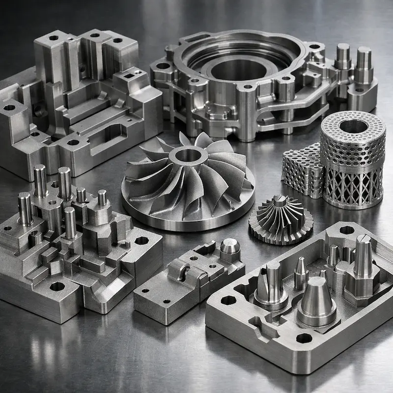
1.2709 Tool Steel SLM metal 3D printing material (1.2709 mold steel / metal additive manufacturing mold steel / mold insert metal printing) is suitable for fixtures, mold inserts and high-strength structural parts. It can realize rapid prototyping of complex cooling channels and integrated structures; finishing is mainly sandblasting and tapping, and supports upload files for a fast quote and delivery.

Tool Steel 1.2709

Tool Steel 1.2709 is commonly used in scenarios requiring high strength and good heat treatment performance, suitable for jigs, mold inserts, and high-strength structural parts.

Mold inserts/jigs and fixtures Complex cooling channels High strength structural parts Metal 3D printing (SLM) Subsequent heat treatment friendly Large finishing space

Quote checklist: Upload your 3D model and, when available, a 2D drawing. Identify the required process, material, quantity, critical dimensions, finish, appearance standard, and target delivery date.

SLM metal 3D printinged mold steel 1.2709 sample: suitable for fixtures, mold inserts and complex cooling channel structures; finishing is mainly sandblasting and tapping, and supports upload files for a fast quote

Key Material and Manufacturing Parameters

Engineering note: Values below are typical reference ranges. Final manufacturability, tolerances, material condition, surface finish, cost, and lead time depend on the drawing, geometry, quantity, and selected process.

Upload CAD files and mark critical features for an engineering review before production.

ProcessSLM Metal 3D Printing (Mold Steel 1.2709)
Material typeMetal | Mold Steel (SLM)
Layer thickness30–50 μm (commonly used; subject to equipment and parameter set)
Dimensional tolerance±0.2 mm (common reference; it is recommended that key dimensions be combined with 2D marking/tolerance requirements)
Minimum wall thickness≥1.0 mm (recommended); affected by the structural shape and forming direction, it is recommended to reinforce or optimize the support strategy for thin-walled/long cantilevers
Minimum aperture/channelIt is recommended that the forming hole/channel be ≥2.0–3.0 mm; the internal flow path must consider the powder cleaning path and necessary powder cleaning holes.
Text/textureRaised character height ≥0.4–0.6 mm; concave character depth ≥0.3–0.5 mm; line width ≥0.35–0.50 mm
Tensile strength1000–1400 MPa (reference range; related to heat treatment status)
Service temperature400℃ (reference)
DensityAbout 8 g/cm³
Surface roughnessSLM surfaces are often rough; critical surface appearance and fit can be improved through sandblasting and subsequent finishing
Recommended useJig fixtures, mold inserts, high-strength structural parts; suitable for complex cooling channels and integrated structures
Assembly and processing Common practice: Leave machining allowance for key hole positions/mating surfaces; it is recommended to go ahead when threaded connections are required. Tapping(Indicate thread specifications and quantity).
FinishingSand blasting and tapping
Typical lead timeRelevant to size, quantity, structural complexity, whether it contains internal flow channels and subsequent processing; clear delivery and expedited options will be given after uploading the file

Finishing

Sandblasting (improved surface consistency)

Used to improve the surface texture and consistency of metal prints and reduce the "graininess" of powder sintering textures; the sandblasting intensity and masking of key surfaces can be selected according to appearance requirements.

Tapping (thread assembly)

Used for threaded assembly and positioning connections; please write down the thread specifications (such as M3/M4/M6), quantity and hole location requirements in the remarks. It is recommended to provide 2D markings for key holes.

Why choose mold steel 1.2709 (SLM)

High-strength route for molds/jigs

More suitable for jigs, mold inserts and load-bearing structural parts; taking into account strength and subsequent processing space, the engineering application direction is clear.

Complex cooling channels and integrated structures

SLM can realize internal flow channels and conformal cooling structures that are difficult to process traditionally, shortening the development cycle and increasing design freedom.

Heat treatment + finishing combined space

The hardness, assembly accuracy and surface quality of key surfaces can be improved through subsequent heat treatment and finishing, making it suitable for projects with high coordination requirements.

Order engineering collaboration is more controllable

Through "definition of critical surfaces + tolerance/datum marking + clarification of tapping requirements", it is easier to lock in risks and delivery standards in advance during the quote stage.

Recommended Applications

  • Jig/Tooling: Requires high strength, dimensional stability, and may have repeated assembly or clamping loads
  • mold insert: Hope to realize complex cooling channels or integrated structures to shorten the development cycle
  • High strength structural parts: Complex structure, strong integration requirements, high traditional processing cost or long cycle
  • Requires subsequent processing and cooperation: Key hole positions, mating surfaces, and threaded connections can be achieved through tapping/finishing

It is not recommended to use it directly (it is recommended to change materials/processes)

  • Extremely mirrored/decorative appearance: Sandblasting alone is difficult to satisfy, additional finishing/polishing strategies are required (it is recommended to communicate appearance standards in advance)
  • Very simple structure and extremely cost sensitive: If there are no internal flow channels/complex features, CNC may be more economical
  • Extremely tight dimensional tolerances and full surface control: It is recommended to plan the machining allowance and benchmark system during the design stage.
  • Closed cavities and cannot clean powder: The risk of residual powder inside is high. It is recommended to add cleaning holes or adjust the structure.

Design and DFM Guidelines

  • Critical surfaces and machining allowances: It is recommended to reserve machining allowance for the mating surface/sealing surface/positioning hole, and mark the datum and tolerance in 2D to avoid the "printed state" being directly used as the assembly surface.
  • Internal flow channel/conformal cooling: Reserve paths and powder cleaning holes for powder cleaning; try to avoid long-distance closures and sharp dead ends in the channel. If necessary, design in sections or add blockable structures.
  • Thin walls and long cantilevers:≥1.0 mm is recommended as a starting point; for thin-walled and long cantilevers, reinforced/rounded transitions are recommended to reduce the risk of deformation and stress concentration.
  • Threads and mounting holes: It is recommended to perform tapping and clarify the thread specifications, hole depth and quantity; it is recommended to provide 2D markings for key holes and explain "assembly hole accuracy is given priority".
  • Surface and appearance standards: Sandblasting can improve consistency, but it is still recommended to finish the key surfaces; if you need to cover some surfaces, please indicate in the remarks (such as sealing surface, positioning surface, mating surface).

FAQs